iGENIX IG9703 Evaporative Air Cooler Repair
This post isn’t accompanied by a YouTube video as I didn’t have time to record the repair; plus, as it was a learning experience, any resulting video would likely have been difficult to follow. On to the content:
Like most city dwellers, I live in an apartment block. Though my lack of a back garden saddens me, there is one perk: people leave broken electronics in the communal areas. In the past, I have repaired and sold 2 TVs, I have scrapped several microwaves, I am currently using a pedestal fan, also found. I dismantled a coffee machine to diagnose the fault and then put it downstairs; it was far beyond safe to use. I've never seen anything so grubby. The point is, a lot of devices break and people often throw them away. Most of the time they can be repaired. I don't go looking for this stuff so finding it is a bonus. Plus, the best way to learn is by practicing on stuff that's already junk.
With the above in mind, I recently found a humidifier. It's proving very handy at the moment as the UK is in the throes of a fairly good summer. Though it is a bit loud it does a great job at cooling my small home office. There are several fan settings, oscillation modes, a large water try and so on; it is feature packed. It originally came with a remote. Mine was missing though it's no hardship to press a few buttons. All in all, it's serving me well. When I found it however, it was faulty. There were multiple faults and they were all with the mains Voltage power supply, an area where my expertise is lacking. I had my fingers crossed it would be an easy fix (those always seem to elude me) and that I could fix it quickly...
Disassembly was easy. I removed the water tray and gave it a quick clean. One of the filters was far past its prime so I threw it away. It isn't essential. Whilst the external parts were drying, I set about removing the screws to gain access to the internals. A simple Philips #1 screwdriver is all I needed for the whole device. The back and front were 2 clearly defined halves and the manufacturer used alignment pegs and screws only. It makes a nice change from the clips typically used to hold modern devices together.
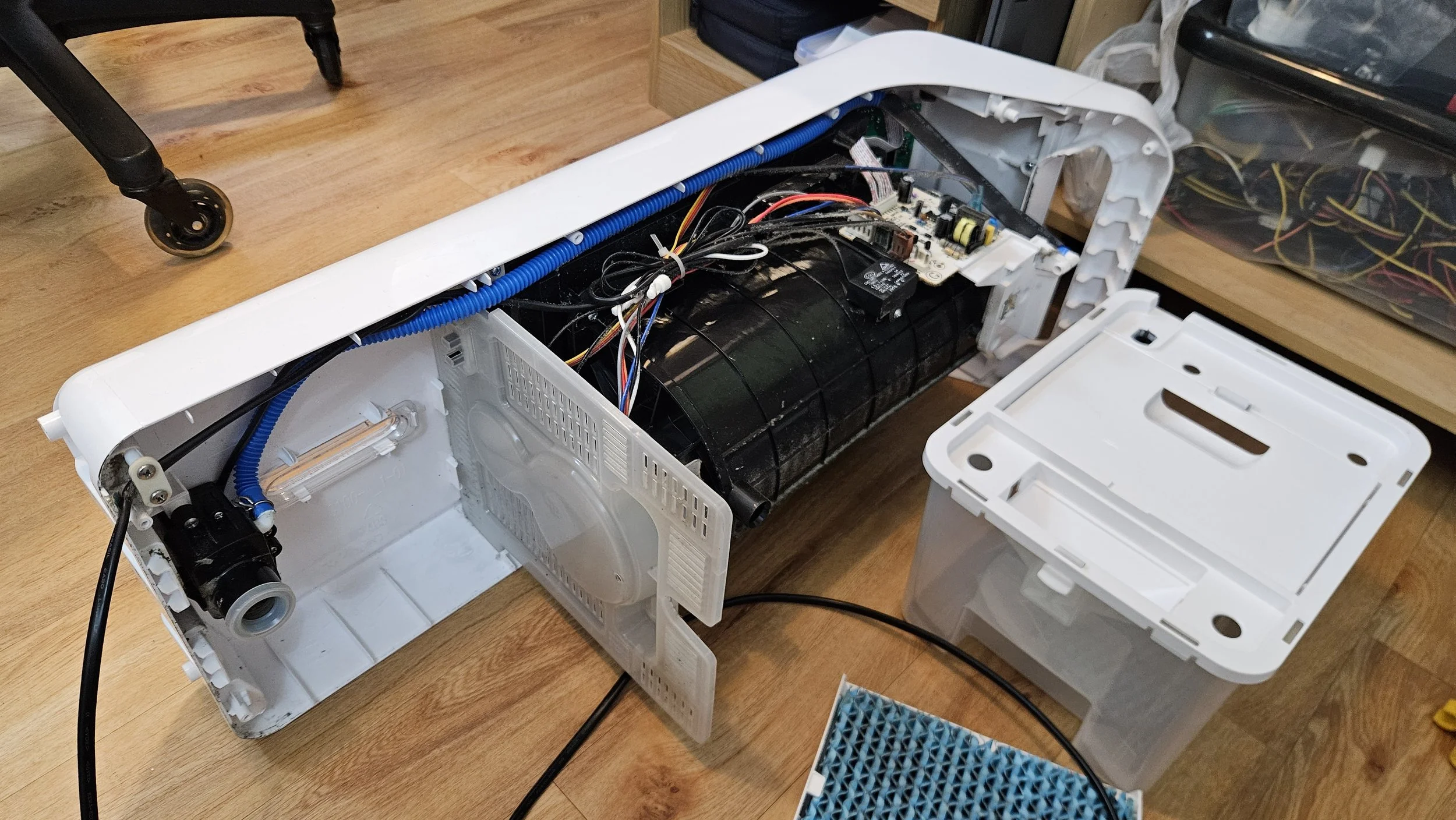
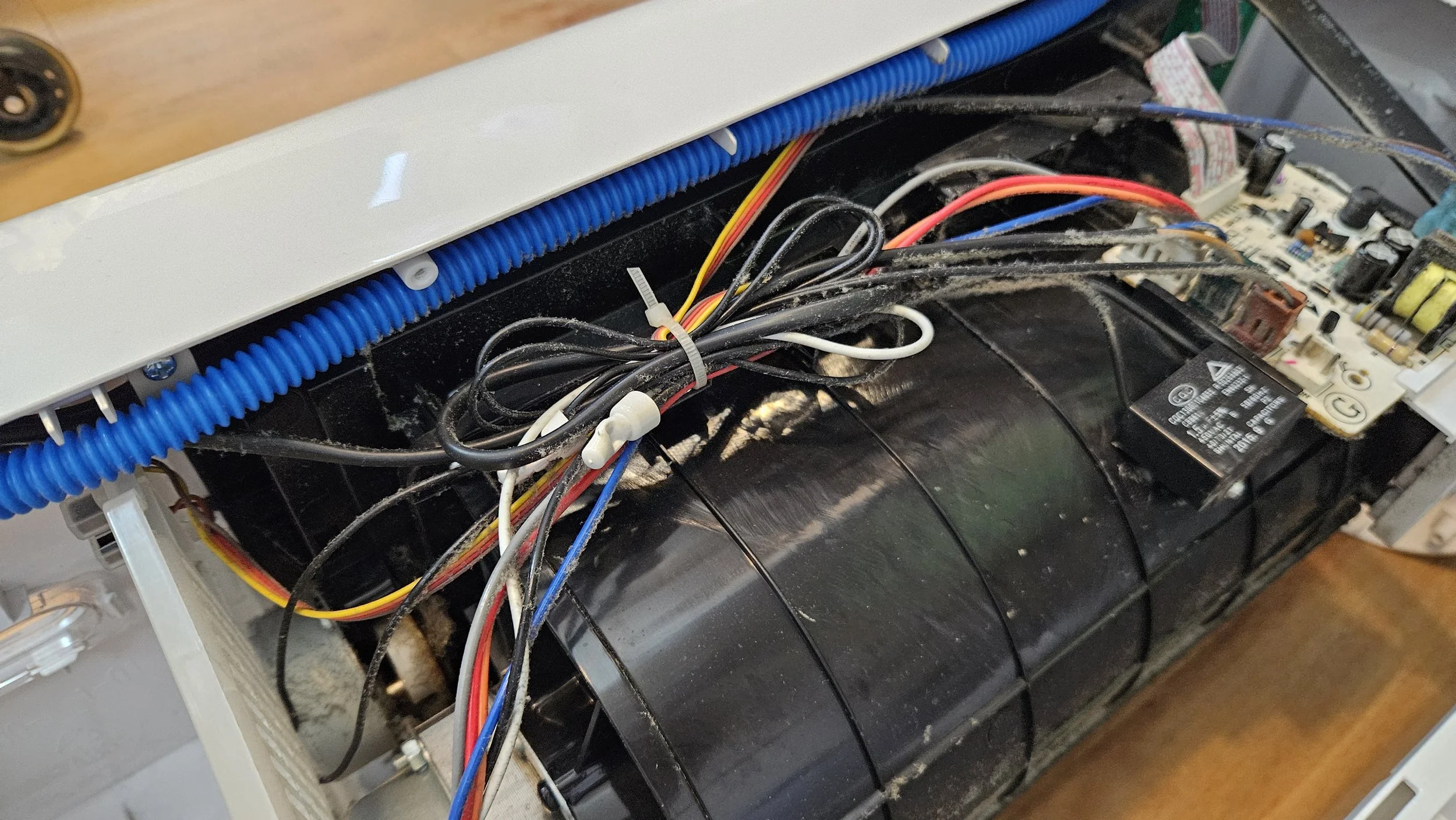
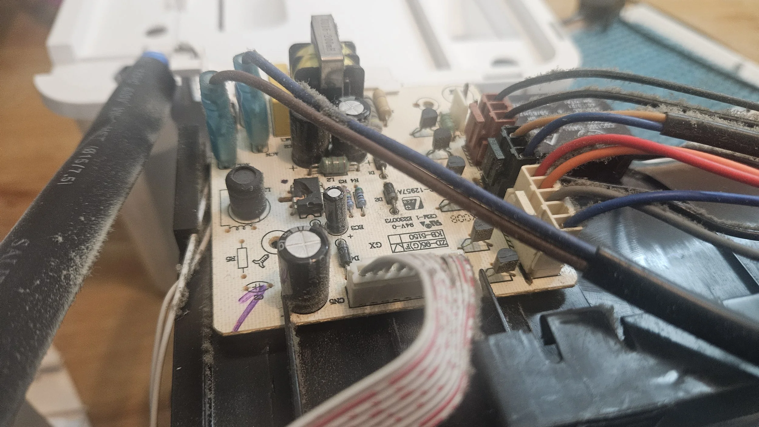
Once inside I did a visual inspection. That's not a step you should skip as it can reveal a lot. It was quite dirty inside but as it has a fan to move air and as it is intended to run for long stretches without a break, I wasn't surprised. Everything looked fine besides the main board. The fan spun freely, none of the connectors were burnt or showing signs of failure, it obviously hadn't been knocked over or had water spilled on it.
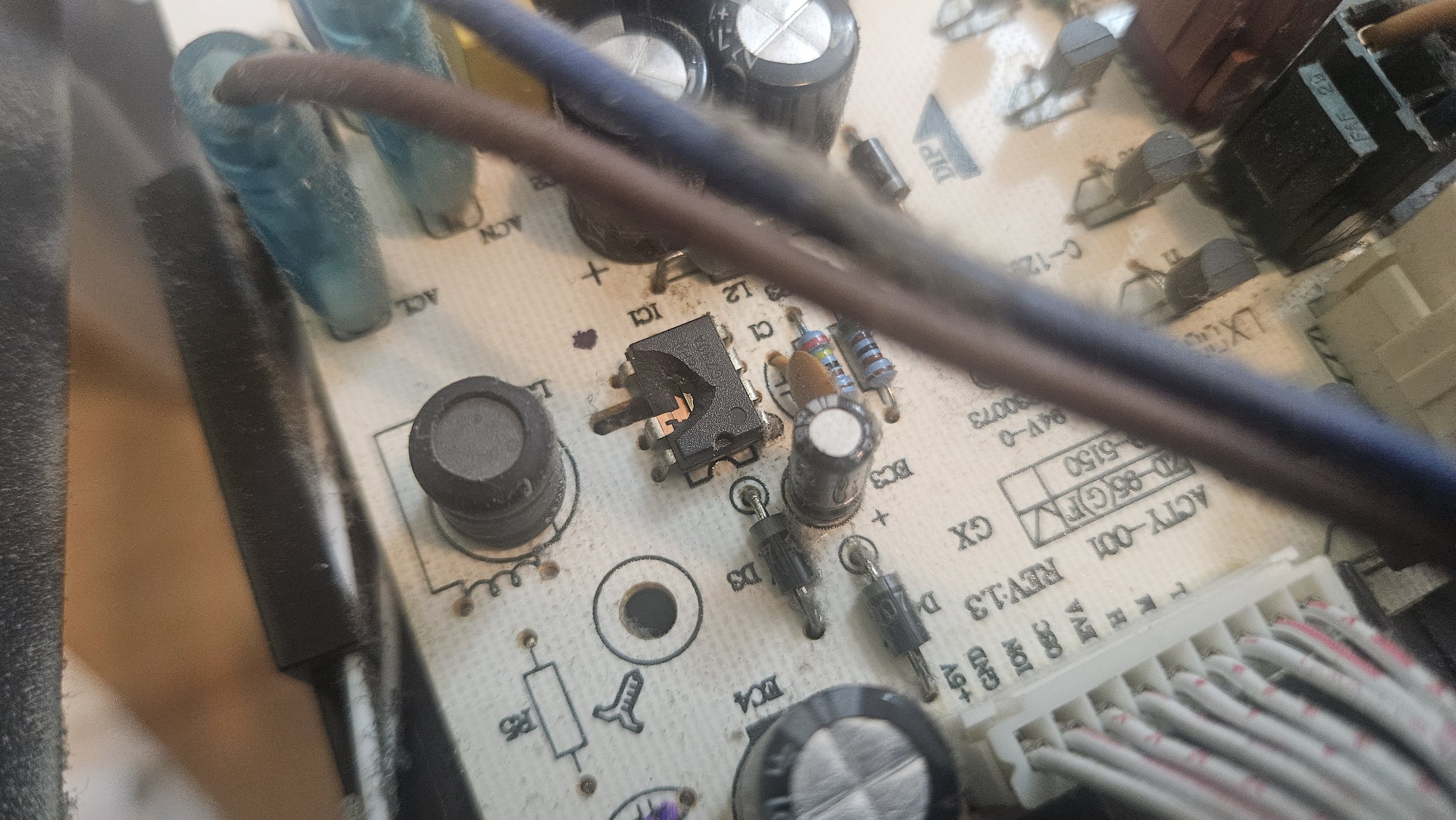
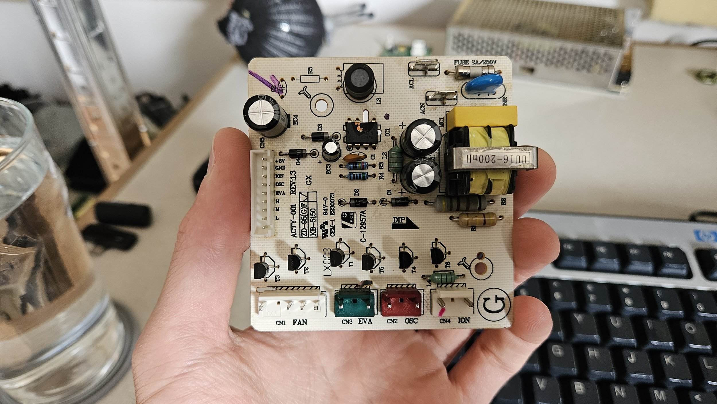
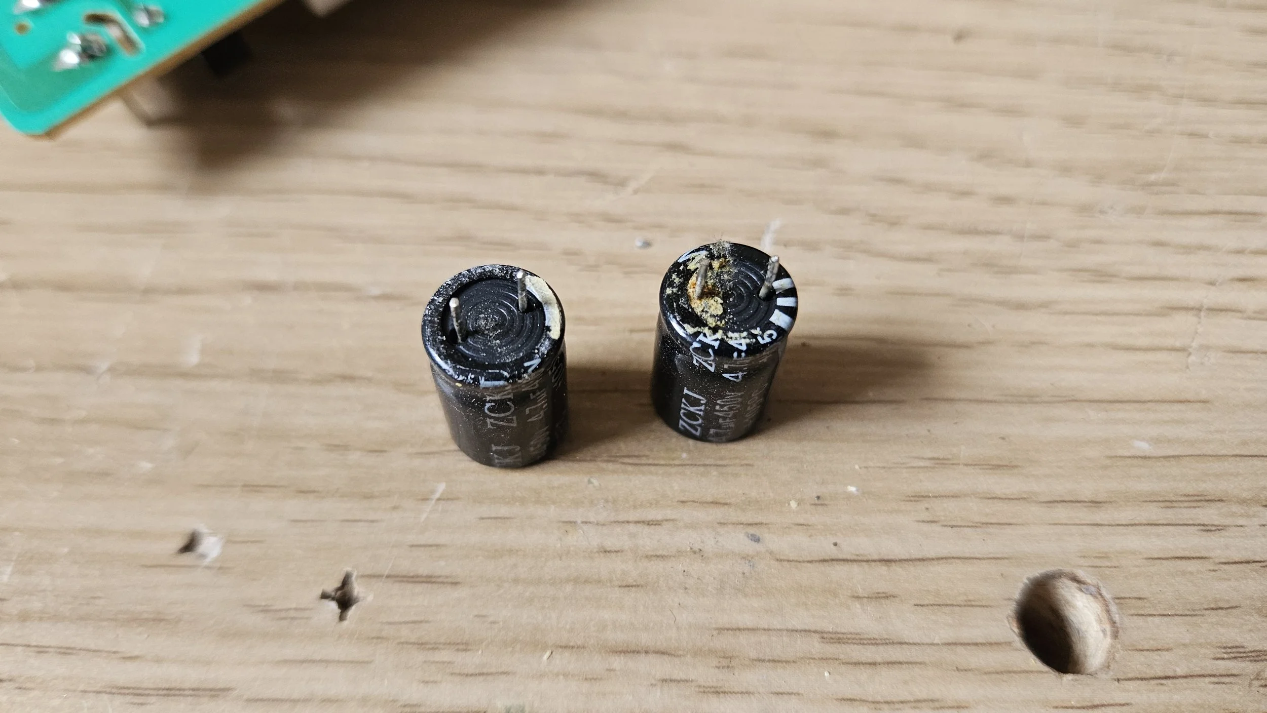
My hopes for a quick repair were dashed when I saw the sorry condition of the main PCB. The main fuse was okay which was a good and a bad thing. The fuse in the plug and on the PCB being okay just means there wasn't enough current to blow them, not that the board is fine. Initially, I found a chip with a hole blown in the side and electrolyte leaking around 2 of the capacitors. The chip was hard but not impossible to identify. Some of the markings survived so I took a hi-res photo and zoomed in. I searched for what I could see and nothing came up so I decided to try AI. AI has made identifying chips much easier but, as with everything it spits out, it's taking a best guess. It doesn't actually know anything. You have to take it's answers with a grain of salt.
My opinion is that, when over-relied on, AI makes people stupider and lazier. When used for every query and when always assumed to be correct, why would you need to think? Just outsource your memory to a Humane AI pin and you're sorted. The sad part is, some people would actually like that. Regardless, I try to use AI as an aid. With it's help I have a starting point. I can then research what I'm told which I had to do extensively for this repair. It's handy when you want a 2nd opinion too but I'll come back to that.
I was able to identify the 7 legged chip as a Power Integrations LNK306PN. I got excited when I found a similar one in my stash but, after skimming the 2 datasheets, it wasn't compatible thus I'd have to buy a replacement. The 2 capacitors beside the same chip were clearly failing as there was electrolyte all around them so they were removed also. The capacitor plague affected an untold number of devices made between 1999 and 2007. Capacitor quality improved for a while but manufacturers started cheaping out again so we have caps which fail a lot more quickly or caps which are simply under-specced for the application. There was a third large capacitor on the board. Visually, it was fine but I replaced it anyway as I had an exact match (spec wise) in my stash. The caps didn't cost anything as they were all removed from failed devices.
If it has just been capacitors and SOP-8 chips, I'd have been happy. My past experience, however, teaches that when a major component fails the surrounding ones are likely to fail imminently (as they get strained by the failure). The best course of action is to replace the other components directly on the path. I used a multimeter and probed about once the chip and capacitors were removed. Surprisingly, the diodes were all okay. I had a resistor which read fine but was visibly burned. Another resistor looked okay on the top and read okay but an inspection revealed there was a hole in the side! If I hadn't noticed, it would likely have took out my other work.
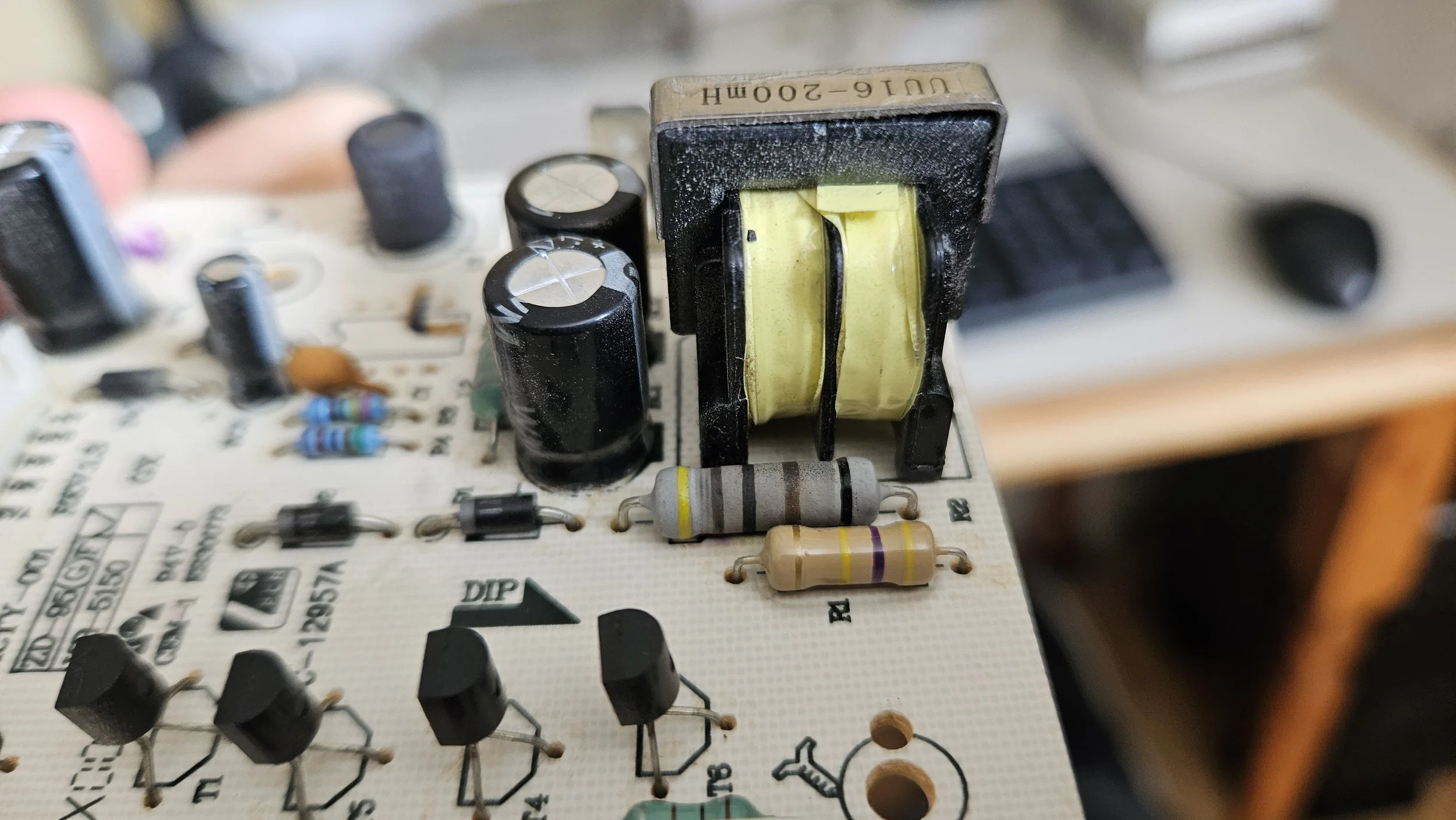
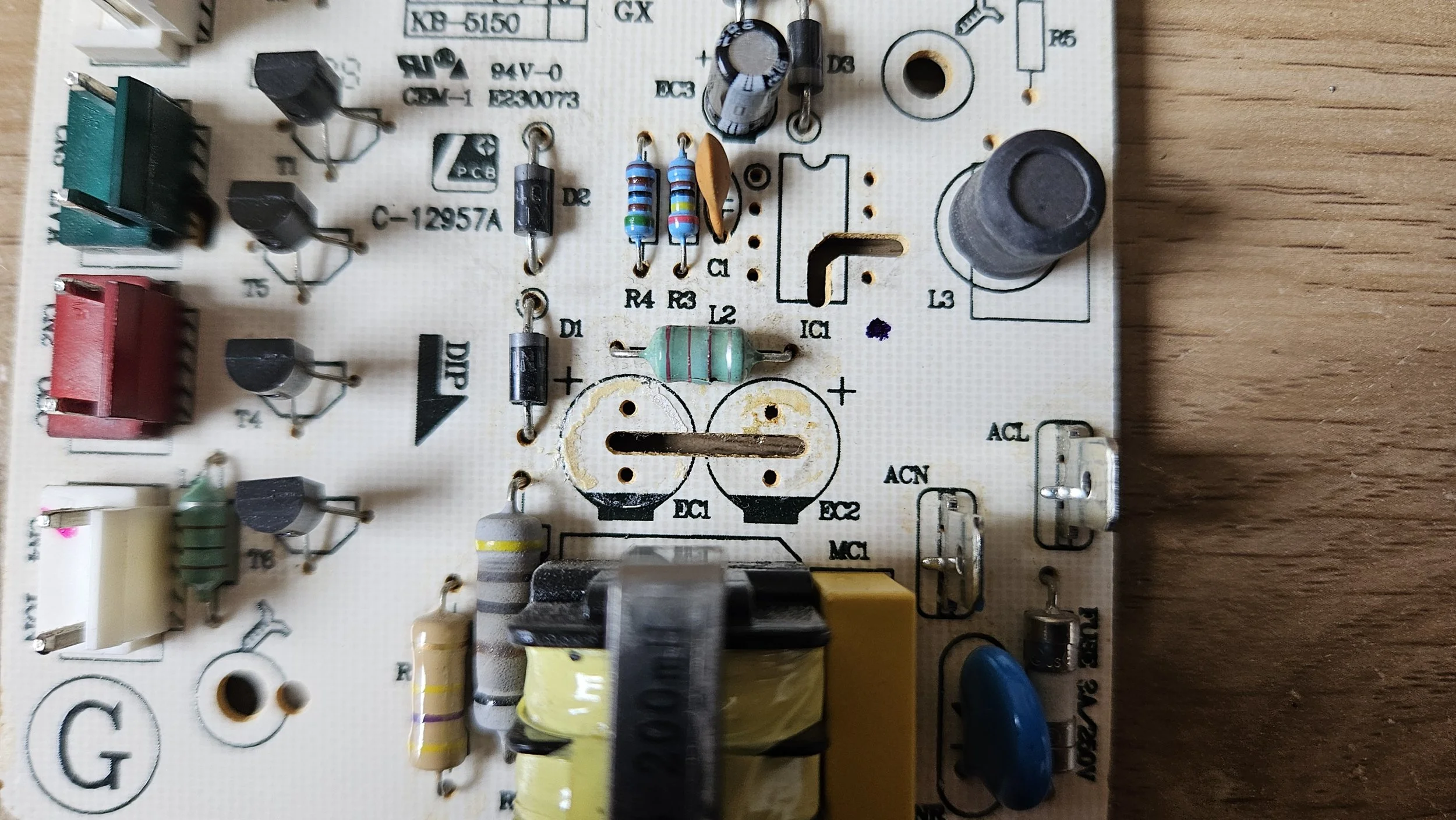
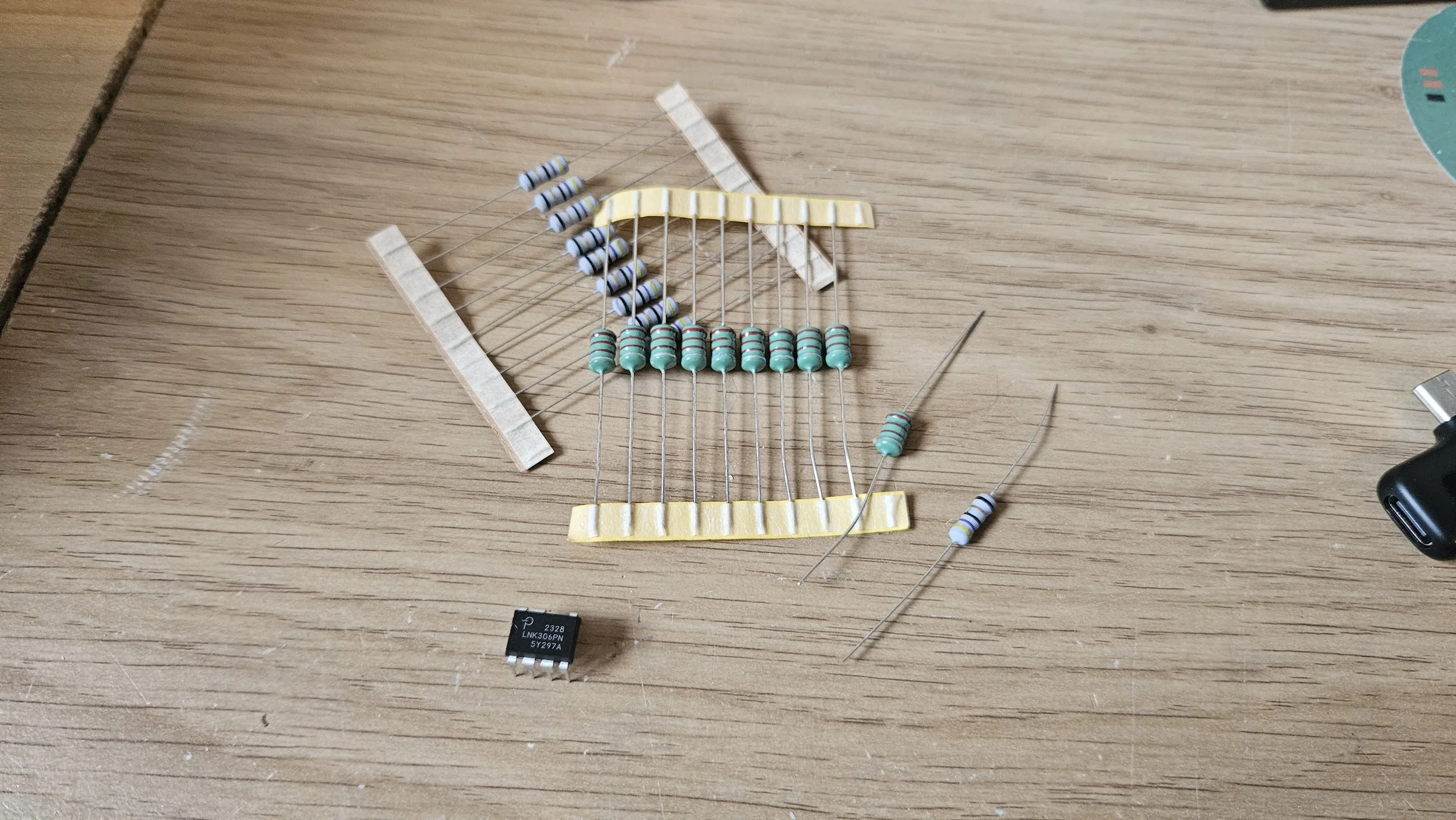
I didn't know the value of either resistor. So I set about trying to identify them. There was the fusible resistor (the burned one) which read 48 Ohms. I searched online and found 47 Ohms was an official value. Whilst mine seemed okay, I exercised caution and decided to buy a replacement. As for the inductor, I had a matching one in my parts bin but it was smaller in size. I suspected it wouldn't be up to the job thus I bought an appropriate replacement. It's worth noting that when I started, I knew very little about resistors and inductors. By the end, I was able to read colour bands, measure them safely, knew what the tolerances were, what causes them to fail and where to buy high quality ones. If I'd only done theory and not practical work, I would have retained much less information.
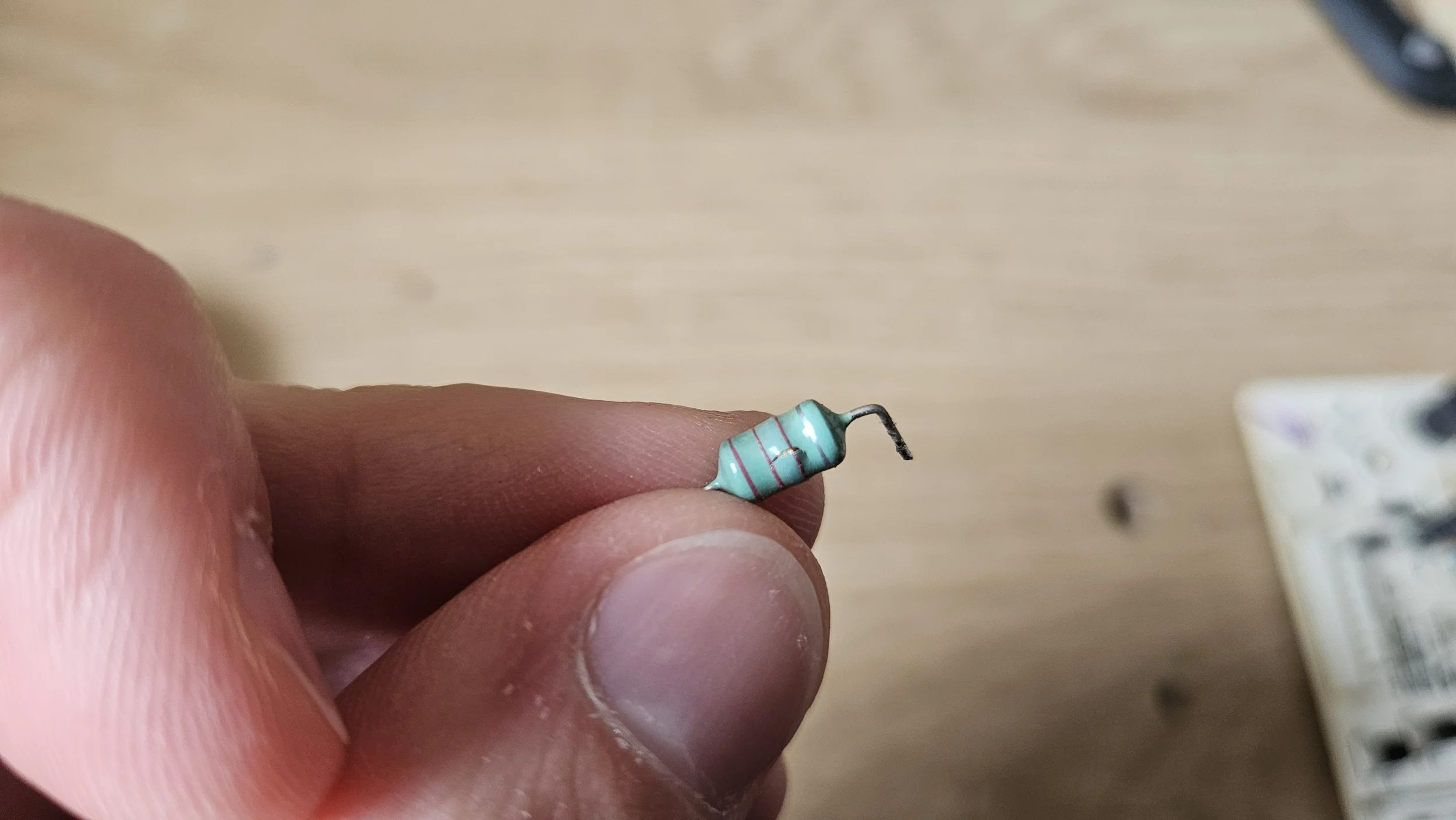
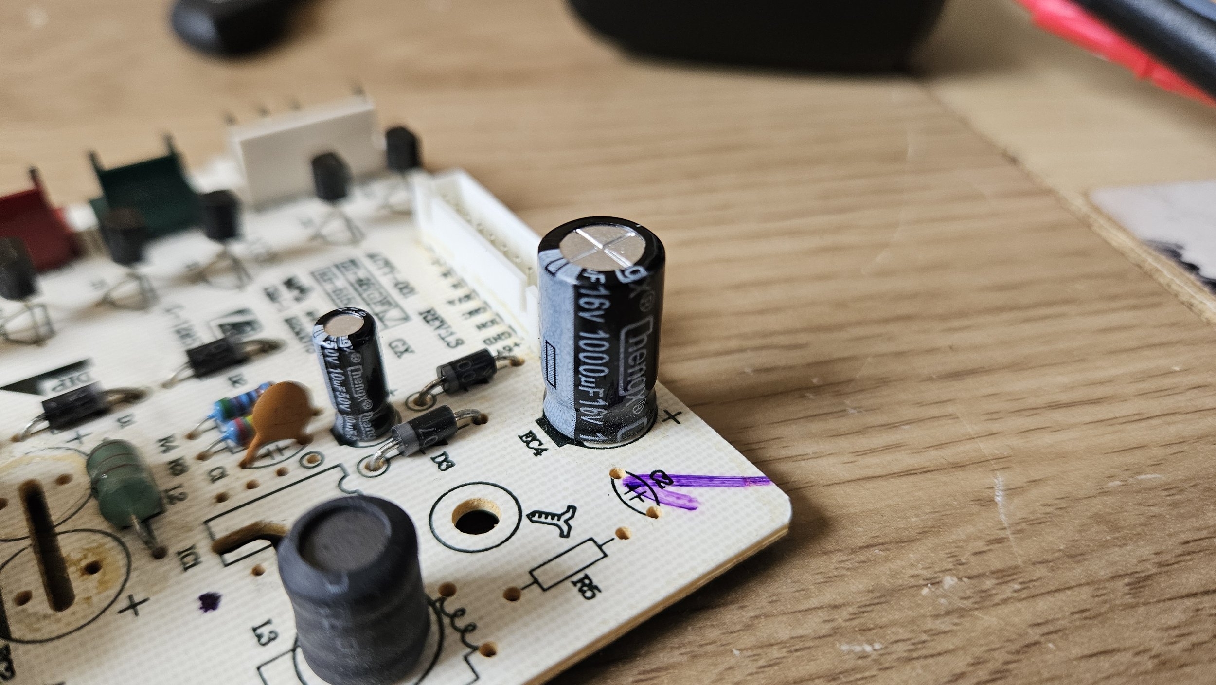
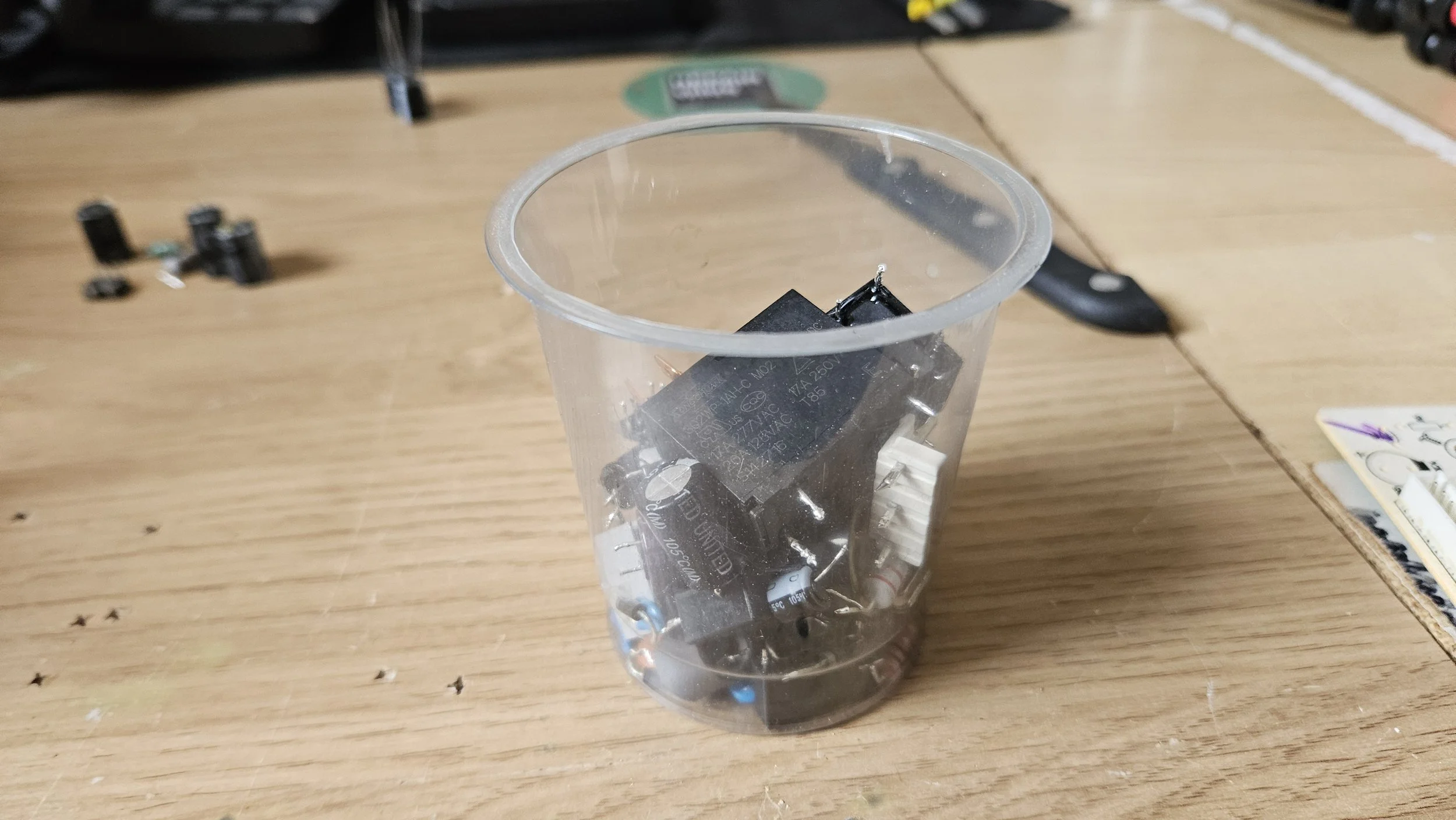
A few days later, the parts arrived. I was excited to get them installed so I jumped right in. I soldered the SOP chip first whilst I had good access. That was simple so next was the resistor and the inductor. I bent the legs in to position and inserted them through the PCB. I envy the people who were technicians in the time that everything was through-hole! It doesn't matter what direction a resistor or an inductor faces so just slap them in. I'd replaced the capacitors earlier but with haste. As I wanted to do a proper job I added a little flux and re-tinned each joint. Then came the clean up. Don't try to get the PCB perfect. You'll be there all day and you'll waste loads of consumables. A small amount of flux residue is acceptable. My preferred method for cleaning is to use a dry cotton bud whilst the board is still warm to absorb the flux. If necessary, I'll use isopropyl alcohol and an old toothbrush.
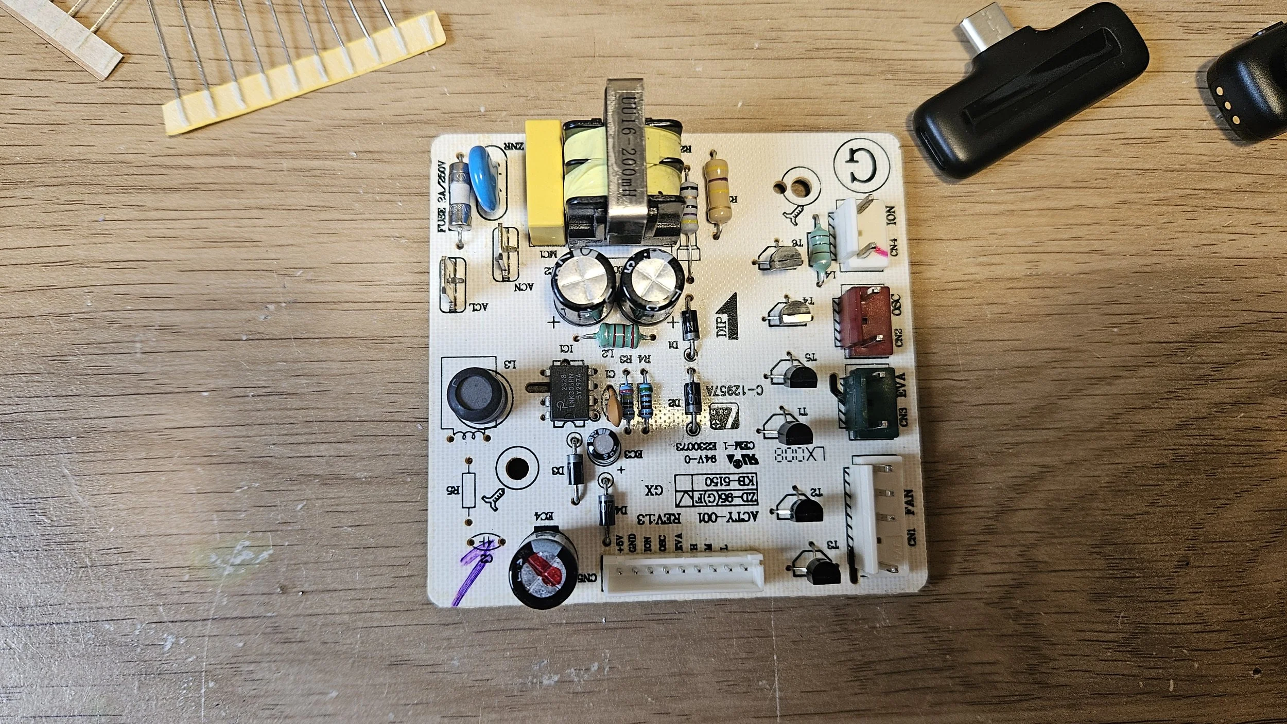
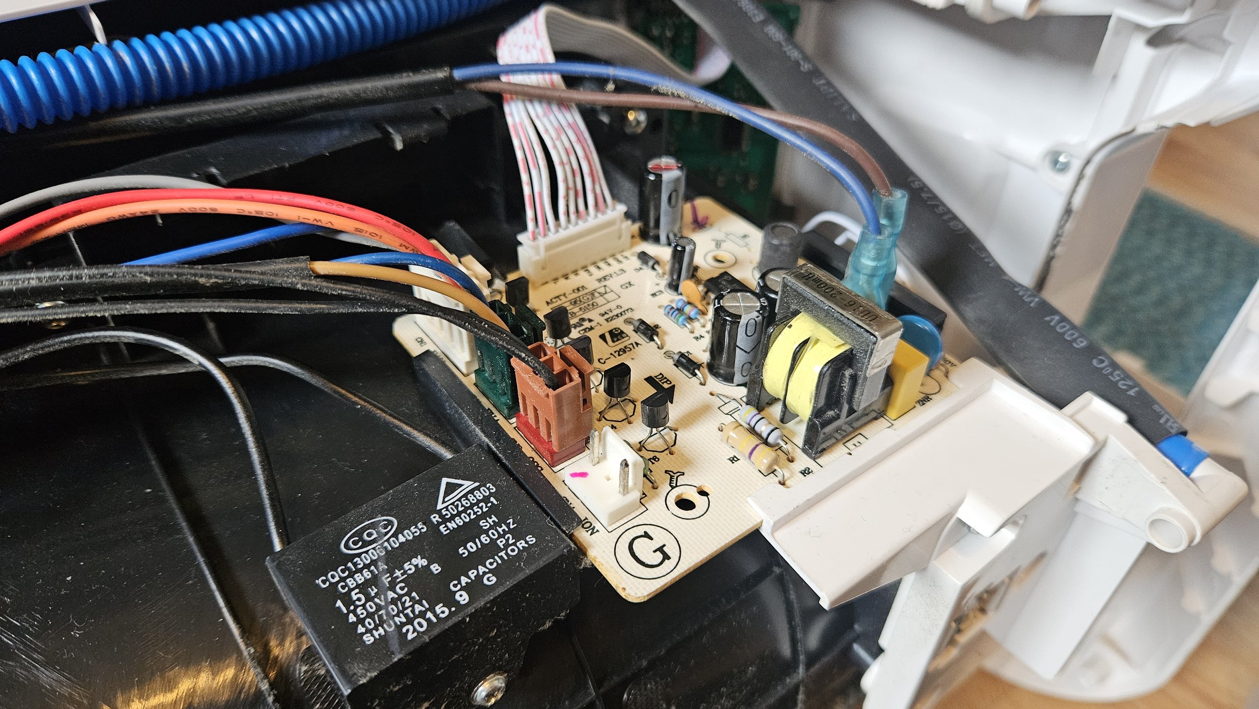
The last step before reassembly was to check the board over. I set my multimeter to diode mode and tested each diode. All good. I put it in resistance mode and tested the resistors. No issues so far. The capactiors weren't short and they'd tested okay prior to install. Finally, I checked the resistors, fuses and inductors. Everything seemed okay. At that point, I was fairly confident it would work. I decided to carry the pieces outside and blast them with an air compressor. Lots of dust came out which is a good thing - I'd rather it be outside than in my flat! The main board was slid in to place, the cables plugged in and the back cover placed on. I put a few screws in so it wouldn't fall apart and installed the water tray.
I plugged it in... It beeped once and didn't do anything. Hmm. I pressed the power button on the control panel and it jumped to life! I let it run for 5 minutes before turning it off at the wall. I hadn't changed any settings but I was now confident everything worked so the rest of the screws went in and I turned it on again. This time I left it running for 30 minutes and went through each setting. So far, I've been using it for a few weeks and it hasn't yet let me down. To the credit of the manufacturer, it worked for 11 years before breaking which is more than can be said of most devices. It was fairly well made although better cooling, more inrush current limitation, higher quality capacitors, etc. could have meant it lasted 30 years.
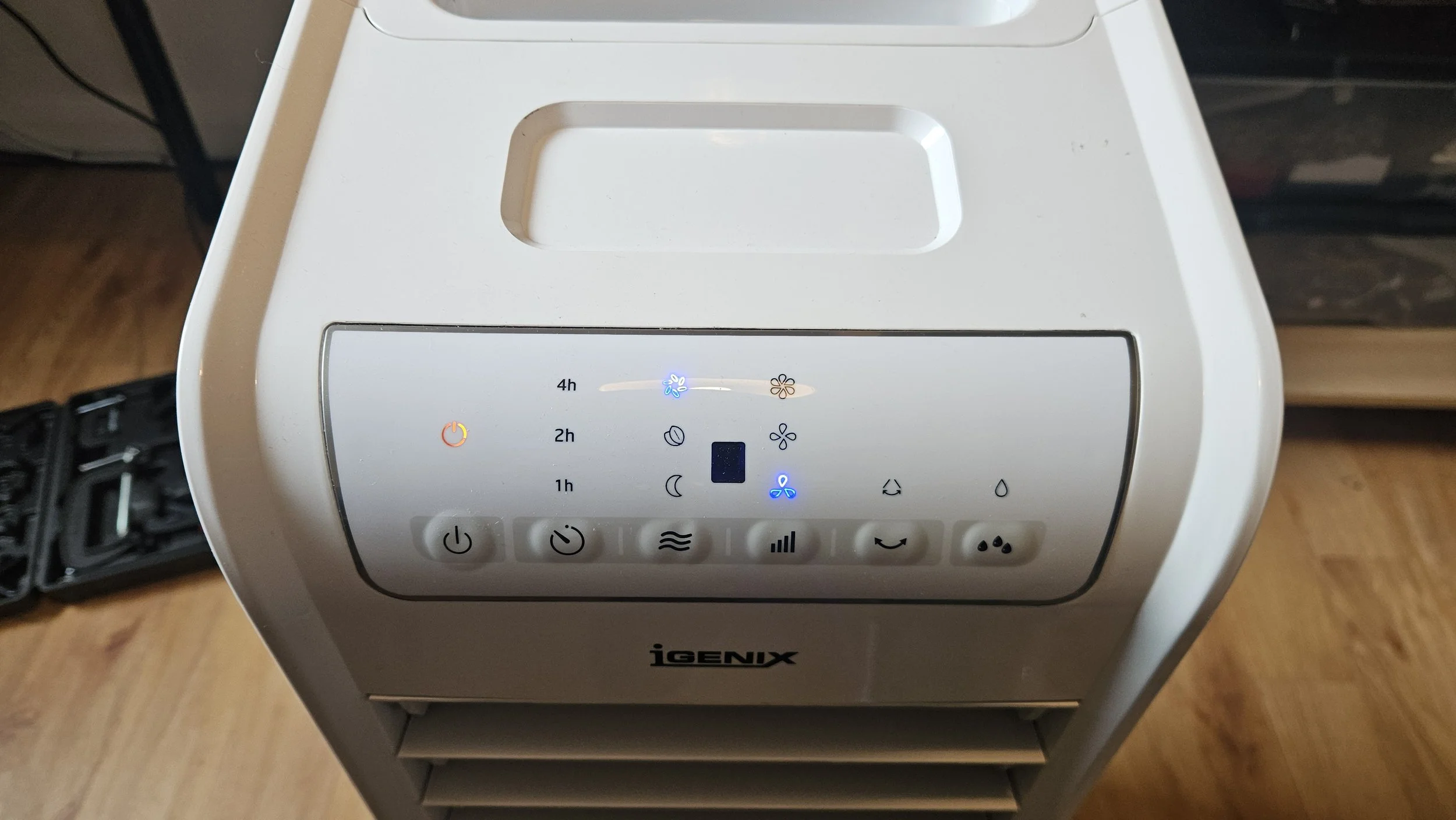
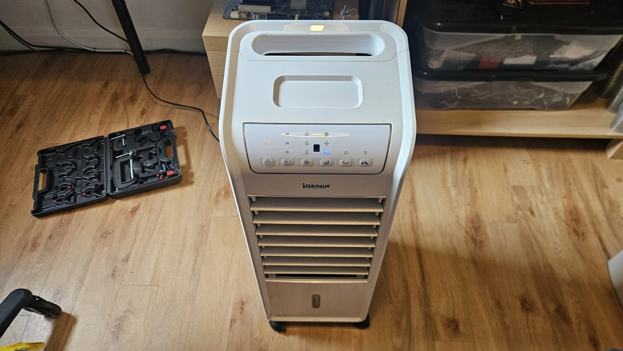
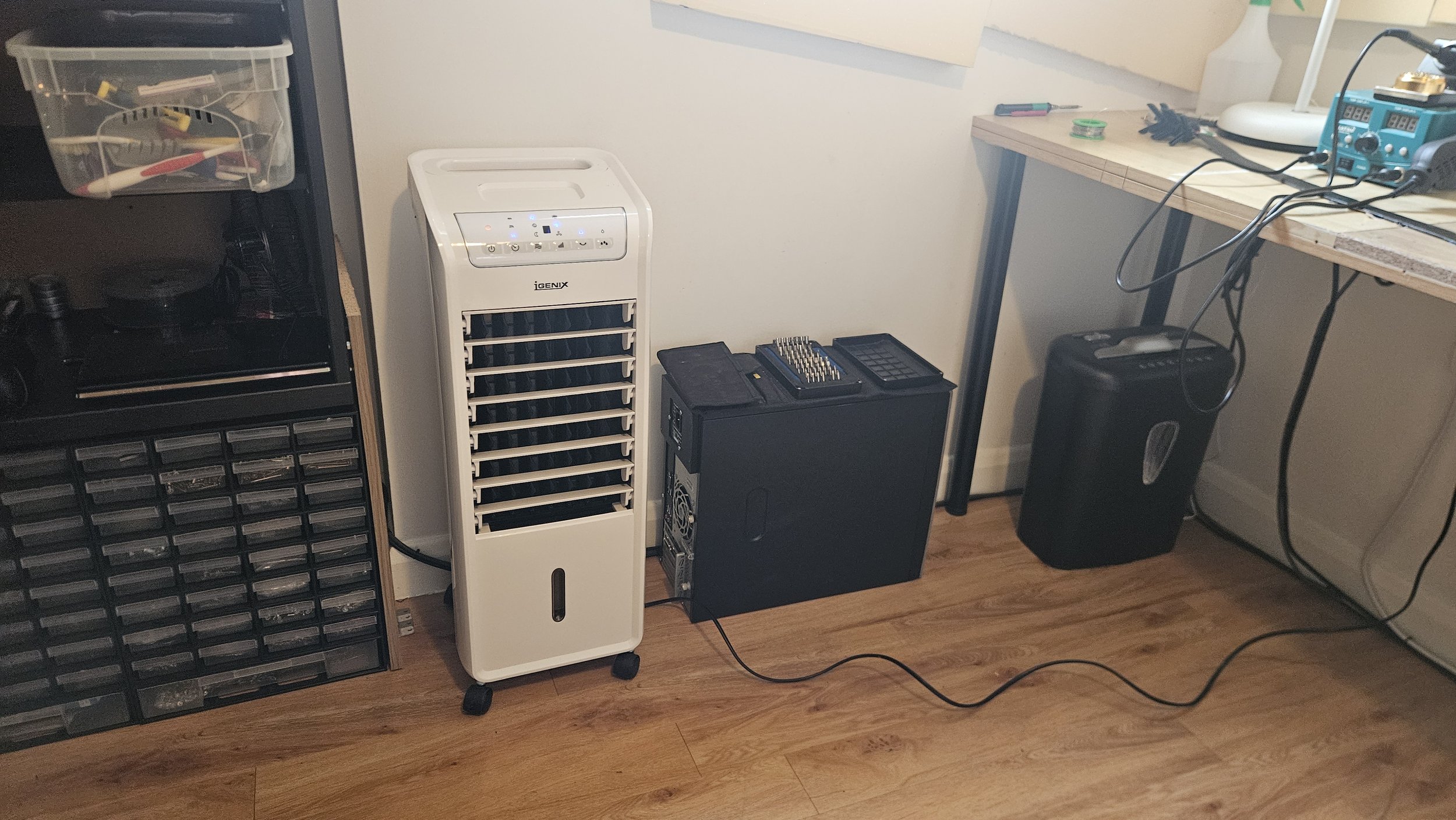
Was the project worth doing then? You can buy a new humidifier for around £80. I spent £12 on the parts and fixing it took 2 hours. Had I been more experienced (which I now am) I could have done it in 30 minutes. I could have done paid repair work in those 2 hours and earnt more than I saved but I would have learnt very little. Like a paid job, I have something tangible for my efforts: a working device. Unlike most paid jobs however, it genuinely taught me some new skills. There was no pressure to fix it quickly or even to fix it at all so I enjoyed working on it. I have 9 inductor coils and 9 fusible resistors spare meaning I'll be able to fix similar devices in the future without having to wait for parts. What I've learnt will carry forward and can be used for other jobs. I'm more confident with mains Voltage now too. In other words, the repair was absolutely worth doing. It's not always just about raw currency.
Thank you for reading. There isn't a YouTube video to accompany this one as I didn't have time to record the process though this is my first blog to feature pictures; I hope to make it so that all future posts have pictures too.
(Repair Wins Blog - Post #9)
(June 2026)